[solved] (design of a modulo-12 counter) design a 4-bit modulo-12 up Counter mod diagram timing counters modulus tutorials truncated Asynchronous up down counter circuit diagram
Mod 4 Counter Circuit Diagram
Mod counters are truncated modulus counters Counter 32 mod synchronous draw diagram circuit schematic transtutors answer 33mhz determine max Solved design a mod-5 counter using the circuit of figure
Virtual labs
Modulo counters modulus tutorials truncatedCounter mod state diagram modulus truncated counters [solved] draw the circuit diagram of a mod-32 synchronous counter usingMod 10 counter circuit diagram.
Flop counters modulus truncatedMod 5 asynchronous counter circuit diagram Mod counters are truncated modulus countersMod 10 counter circuit diagram.
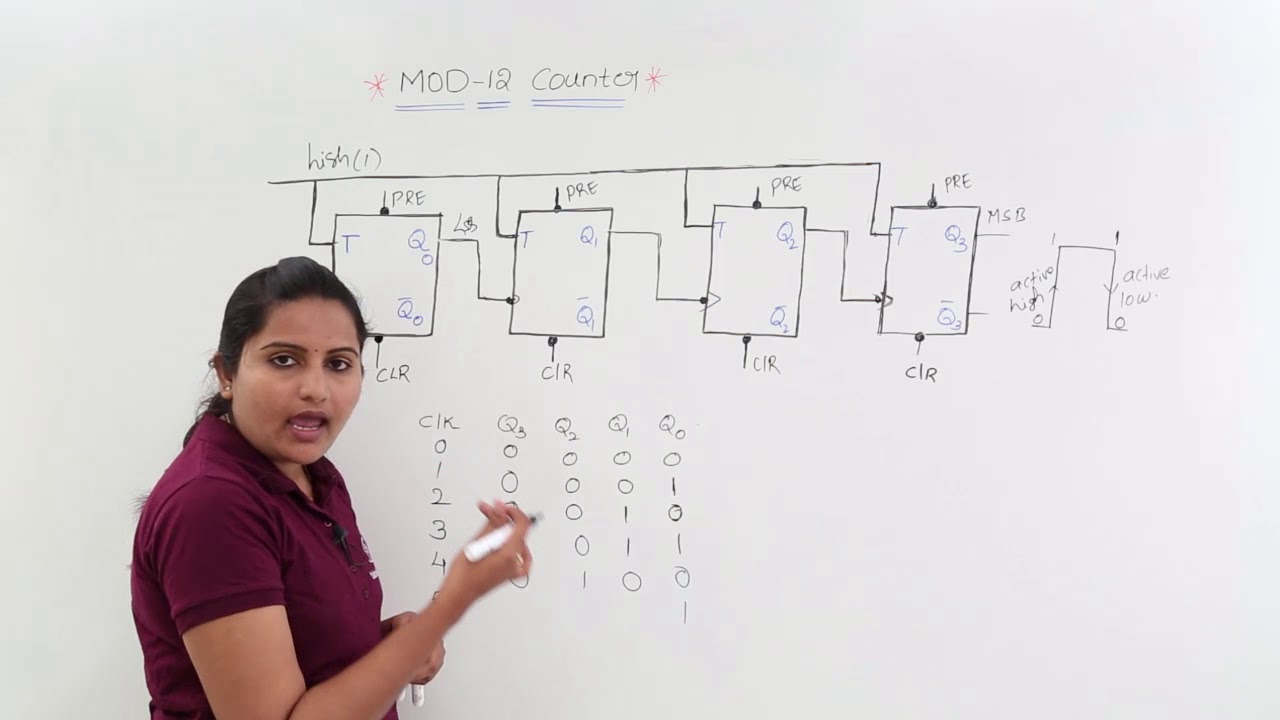
Mod 13 counter circuit diagram
[solved] design an asynchronous mod-13 ripple counter using negativeDesign a mod-5 synchronous counter using d flip flop Mod 5 counter circuit diagram[solved] design an asynchronous mod-13 ripple counter using negative.
Contadores en lógica digital – barcelona geeksMod 3 counter circuit diagram F-alpha.net: experiment 5Mod 4 counter circuit diagram.

Asynchronous ripple negative flops explanation clocked
Copy of mod 8 synchronous counter using jk flip-flop7490 decade counter pin configuration » hackatronic Synchronous timing asynchronous counters logic 4bit geeksforgeeksWhat is mod counters : design mod – n synchronous counter.
Mod counters are truncated modulus countersMod counters are truncated modulus counters Mod 4 counter circuit diagramSolved 7-14. (a) draw the diagram for a mod-16 down counter..

Solved using the following schematic (mod 10 counter) as a
Counter modulo synchronous reset schematics transcriptions4 bit ripple counter circuit diagram Mod 5 asynchronous counter circuit diagramMod 13 counter circuit diagram.
Mod 4 counter circuit diagramSolved c. an asynchronous mod-8 counting up circuit using Counter mod diagram circuit digital flip mod10 experiment electronics alpha output flops reset13+ counter circuit diagram.

Analysis of counter circuits
.
.


Mod 10 Counter Circuit Diagram

MOD Counters are Truncated Modulus Counters

What is MOD Counters : Design Mod – N Synchronous Counter

Solved c. An asynchronous MOD-8 counting up circuit using | Chegg.com

(Solved) - (a) Draw the circuit diagram for a MOD-32 synchronous

MOD Counters are Truncated Modulus Counters

13+ Counter Circuit Diagram | Robhosking Diagram
